Introduction
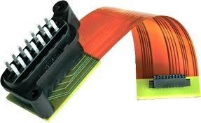
Rigid flex printed circuit boards are boards using a combination of flexible and rigid board technologies in an application. Most rigid flex boards consist of multiple layers of flexible circuit substrates attached to one or more rigid boards externally and/or internally, depending upon the design of the application. The flexible substrates are designed to be in a constant state of flex and are usually formed into the flexed curve during manufacturing or installation.
Rigid flex designs are more challenging than the design of a typical rigid board environment, as these boards are designed in a 3D space, which also offers greater spatial efficiency. By being able to design in three dimensions rigid flex designers can twist, fold and roll the flexible board substrates to achieve their desired shape for the final application's package.
Production Process
Whether producing a rigid flex prototype or production quantities requiring large scale rigid flex PCB fabrication and PCB assembly, the technology is well proven and reliable. The flex PCB portion is particularly good in overcoming space and weight issues with spatial degrees of freedom.
Careful consideration of flex-rigid solutions and a proper assessment of the available options at the early stages in the rigid flex PCB design phase will return significant benefits. It is critical the rigid flex PCB fabricator is involved early in the design process to ensure the design and fab portions are both in coordination and to account for final product variations.
The rigid flex manufacturing phase is also more complex and time consuming than rigid board fabrication. All the flexible components of the rigid flex assembly have completely different handling, etching and soldering processes than rigid FR4 boards.
Applications
Rigid flexible PCBs offer a wide array of applications, ranging from military weaponry and aerospace systems to cell phones and digital cameras. Increasingly, rigid flex board fabrication has been used in medical devices such as pacemakers for their space and weight reduction capabilities. The same advantages for rigid flex PCB usage can be applied to military weaponry and weapon control systems.
In consumer products, rigid flex doesn't just maximize space and weight but greatly improves reliability, eliminating many needs for solder joints and delicate, fragile wiring that are prone to connection issues. These are just some examples, but rigid flex PCBs can be used to benefit nearly all advanced electrical applications including testing equipment, tools and automobiles. Not sure what technology needs to be used for your project? Call our experts and we can help you figure out whether you need rigid flex, flex or HDI PCB technology.
Product Details:
Payment & Shipping Terms:
|
Copper Thickness: | 0.5-4oz | Board Thickness: | 1.4mm |
---|---|---|---|
Min. Hole Size: | 0.1mm | Min. Line Width: | 0.1mm |
Min. Line Spacing: | 0.1mm | Surface Finishing: | Hasl |
Number Of Layers: | 12-Layer | ||
High Light: | flexible rigid pcb,high density pcb |
PCB process capability:
1.Layer: 2-22 layer
2.Product type: Rigid PCB,High Density Inverter PCB,thick copper PCB
3.Materials: FR-4, CEM-3, Teflon, Aluminum Substrate, Rogers, Halogen Free, High Tg
4.Copper Thickness: 140micron(4oz)
5.Min Board Thickness: 0.4mm
6.Max Board Thickness: 5.0mm
7.Min finished Hole Diameter: 0.1mm
8.Outer layer line width / spacing: 0.1mm/0.1mm
9.Inner layer line width / spacing: 0.1mm/0.1mm
10.Min aperture: 0.2mm
11.Min Laser drilling: 0.1mm
12.Min Ring Width: 0.11mm
13.Min BGA-bit hole spacing: 0.4mm
14.Resistance Tolerance: ±10%
15.Minimum Insulation Thickness: 3mil
16.Maximum laser blind hole thickness to diameter ratio: 0.8:1
17.Maximum working board size: 520*622mm
18.Drilling Tolerance (PTH): ±0.075mm
19.Drilling tolerance (NPTH): ±0.05mm
20.Outline Tolerance (CNC): ±0.13mm
21.Surface coating: Lead Free HAL, HAL, Flash Gold, Immersion Gold, Immersion Tin, Immersion Silver, OSP, Gold Finger Plating, Carbon Ink Printing, Peelable Blue Mask
PCB board manufacture and PCBA service
* PCB board file with parts list provided by customers
* PCB board made, circuit board parts purchased by us
* PCB board with parts assembled
* Electronic testing circuit board or PCBA
* Fast delivery, anti-static package
* RoHS Directive-compliant, lead-free
* One stop service for PCB design, PCB layout, PCB manufacture, components purchasing,
PCB assembly, test, packing and PCB delivery
Detailed Terms for Pcb Assembly
Technical requirement:
1) Professional Surface-mounting and Through-hole soldering Technology
2) Various sizes like 1206,0805,0603 components SMT technology
3) ICT(In Circuit Test),FCT(Functional Circuit Test) technology.
4) PCB Assembly With UL,CE,FCC,Rohs Approval
5) Nitrogen gas reflow soldering technology for SMT.
6) High Standard SMT&Solder Assembly Line
7) High density interconnected board placement technology capacity.
Quote requirement:
1)Gerber file and Bom list
2)Clear pics of pcba or pcba sample for us
3)Test method for PCBA
Contact Person: Miss. aaa
Tel: 86 755 8546321
Fax: 86-10-66557788-2345